2 PCMCIA Card Slots
Realize the Apex III/IV potential for multiple data collection applications through the use of the 2 PCMICA card slots that can be quickly and easily configured in the field.
Wired-Line Modems
The use of wired-line modems is a popular application for which the Apex is very well suited. The Apex can easily be fitted in the field with a PC Card modem with a connector. The connection between the modem's X-Jack connector and RJ-11 wall phone jack connector is made complete using the Apex Modem EndCap (Compsee part number 0220603) and a standard RJ-11 style phone linecord (usually supplied with a new modem).
Most PC Card Modems that are PCMCIA 2.0 will work with the Apex. Compsee has had positive experiences with the following two cards -
- US Robotics (3-Com) Model XJ1560J
- Megahertz Model XJ2288
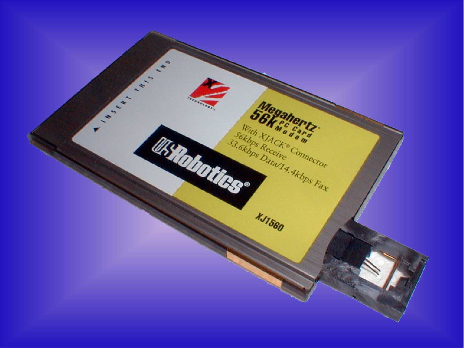 This application note will cover some considerations when using PC Card Modems. When selecting a modem, other than those mentioned above, the user should take care to ensure the modem selected has the ability to be placed under software control into a "sleep mode" or other power savings mode, when not in use. This is critical to ensure adequate battery life with the modem installed into the Apex. Failure to follow these guidelines will result in decreased battery life. The photo on the right depicts the US Robotic Model XJ1560J PC card Modem with the connector extended.
Modem EndCap
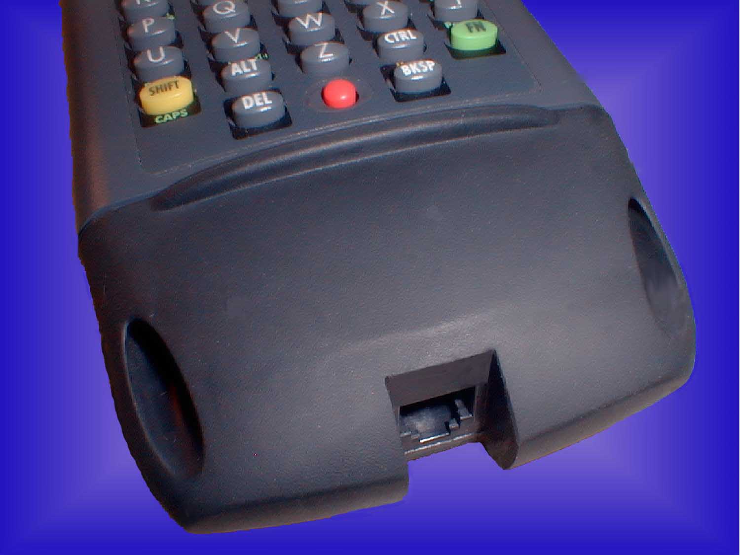
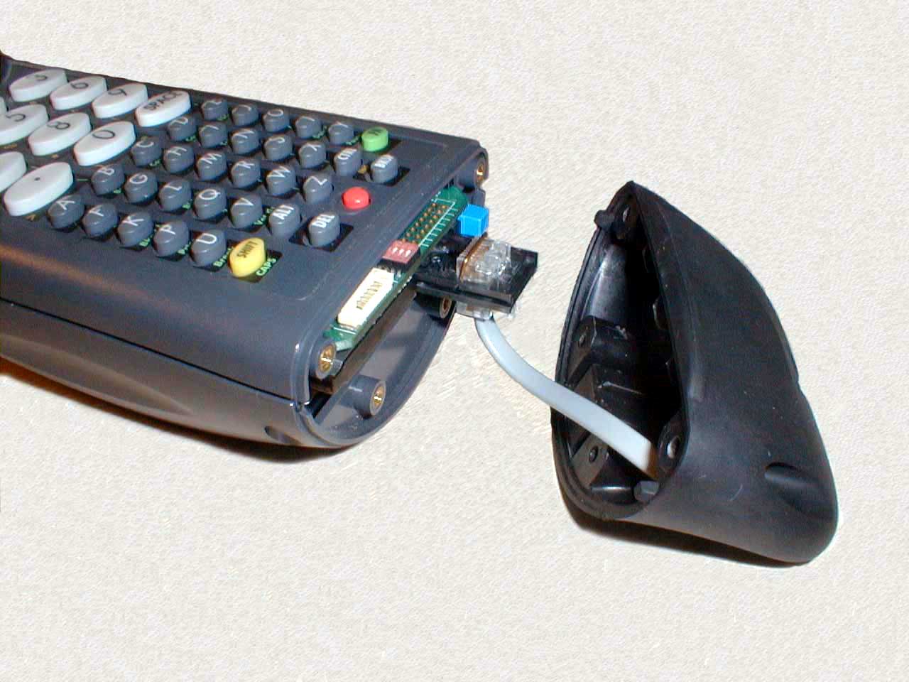 The following two photos depict the Apex with a PC card modem installed. The first picture shows the Apex with the four mounting screws removed. These screws hold the Endcap in place. As you can see, the PC card modem has a style connector that is spring-loaded and extends from the body of the modem card by simply pushing in and releasing the connector. The second photo shows the Apex with the Modem EndCap installed.
Mechanical Installation
- Deploy the x-jack connector
- Plug in the short RJ-11 cable from the Modem EndCap into the connector on the modem
- Verify all internal connections are complete
- Carefully align the Modem Endcap to the mounting holes
- Verify that the wire is not crimped or otherwise misaligned
- Replace and tighten all four mounting screws on the Apex
Power Conservation
 Because the PC Card Modem is powered by the Apex Battery Pack, it is important to take precautions to avoid any unnecessary load on the battery. As such, the modem should be forced into a "sleep mode" or other power-conserving mode, whenever the modem is not in use. The programming method(s) you may use to accomplish this may vary. Please consult the manufacturer's technical documentation in regard to power management for the modem you choose.
The Apex should be configured in a mode that will draw the least amount of power. The following are some tips that will prolong battery life if correctly implemented in the Apex configuration.
- TURN OFF the scanner aiming beam (bcdriver aimtm=0) if an aiming beam is not required by the application. If an aiming beam is required, use the shortest acceptable duration.
- SET scanner beeper duration (bcdriver beep=ms,freq) as short as acceptable.
- TURN OFF the infrared port (ir off) when not in use.
- TURN OFF the backlight (<FN>+<L>) when not in use.
- POWER OFF the unit (<FN>+<Power>) when the unit will not be used for an extended period.
- ENABLE BIOS Power Management and set the timeouts as short as acceptable.
- DO NOT perform any unnecessary "activities" in the background. Activities are indications that the system is doing something and the processor needs to be operating at the highest speed. Activities reset mode timers and cause a transition from Low Speed mode or Standby mode to High Speed mode. Activities include
- Any Key press
- CPU access to on-board Flash (A-drive and C-drive)
- Serial Port access
- UART's serial input pin (SIN)
- ACIN (unit is in Dock)
- DMA request
- CPU access to IDE hard drive registers
- CPU access (memory or I/O) to PC Cards
- PC Card change interrupt
- CPU access to internal graphics (reading or writing to the display)
Compsee has also provided an Application Programming Resource (APR-C) written in "C" that will significantly improve power management in this and other power sensitive applications. These "APR-C" can be downloaded from the Compsee Website.
Technical Assistance:
Users requiring Technical Assistance should contact
Compsee Technical Support at 1-800-628-3888. Technical questions can
also be e-mailed to [email protected].